Our newest CIPP units provide the one thing that is most needed in this industry – Efficiency. Heater efficiency is the key to profitability and our new Gen II models offer the best available.
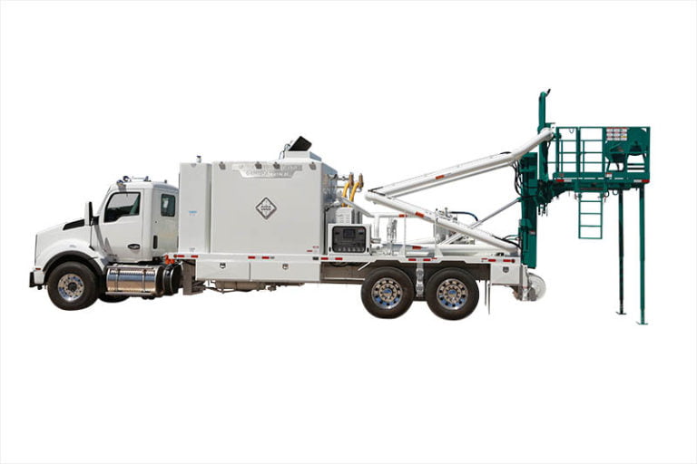
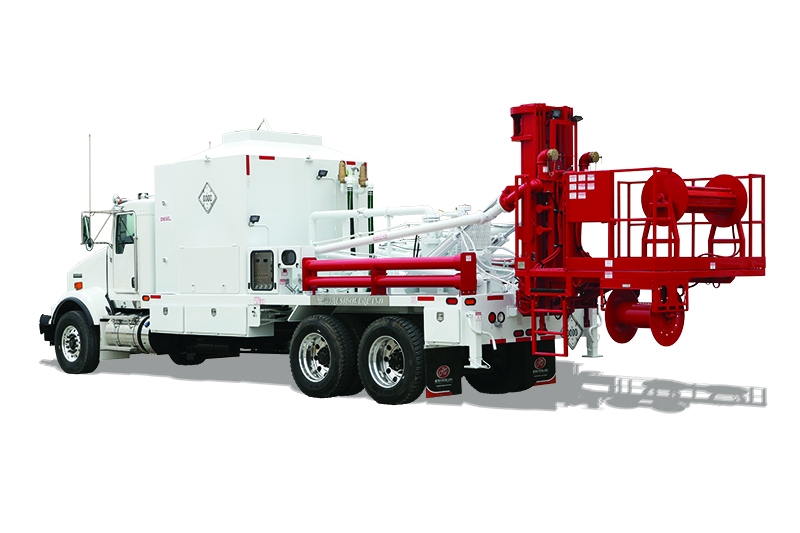
GEN II Heater with Work Platform
- Unit is Constructed on 10″ I-Beam Frame with 10″ I-Beam Crossmembers
- 5″ Channel Outriggers
- 1/4″ SA36 Carbon Steel Floor Plate
- 8″ Square Tubing Re-Enforcement for Lift Assembly
Burner Features:
- Two Burners Size 5-P Oil-Fired Burners with Full Proportioned 3 to 1 Turn Down Ratio
- 13,000,000 Combined BTU Input
- Hydraulic Driven Internal Combustion and Atomizing Air Blower
- Direct Fire Ignition
- Low Water Flow Shutdown and High Temperature Shutdown Systems
- All Weather Burner Covers
Heat Exchanger:
- 3″ SA106 Grade B Seamless Tubing
- The Heat Exchanger is constructed in a Two-Pass Arrangement and is Fed by a 4″ Header which Separates the Flow into Two-paths through the Helical Coils and an Economizer
- Heat Exchanger is Constructed to ASME Code Sect. IV Specifications and Stamped with the “H” Symbol
- The Heater will be Registered with The National Board
- Data Reports will be Furnished
Burner Chamber:
- 1/4″ SA36 Carbon Steel Outer Walls
- Three Layers of Ceramic Fiber Insulation Attached to the Interior Walls Rated at 2,300 Degrees Fahrenheit Per Layer
- Insulated Burner Chamber Top with an Automatic Exhaust Door
Fuel Storage Tank:
- 670 Gallon Fuel Storage Tank Constructed of 1/4″ SA36 Carbon Steel
- Tank Fully Baffled with 3/16″x 6″ SA36 Carbon Steel Plate
- 3″ Fill Neck with Ladder Access on Passengers Side
- Shut-Off Valves and Spin-On Filters Located on Drivers Side for Easy Access and Maintenance
Control Panel:
- Water Tight Control Box with Full Viewing Plexi-Glass Window
- Two E-110 Fireye-Flame Monitoring System with Digital Display Readout for Constant Burner Status Monitoring
- Watlow Temperature Controller to Control Discharge Temperature
- Digital Display Flow Meter for Continuous Monitoring of Water Flow thru the Heater
- Low Flow Safety Switch to Shut-Down Burner if Water Flow is Lost
- Control Power Switch with Indicator Light
- Burner #1 and Burner #2 On/Off Switches with Indicator Light
- Work Lights Switch with Indicator Light
- Control Panel Light Switch with Indicator Light
- Remote Power Switch for Cab Mounted Inverter Power Supply
- Digital Fuel Level Indicator
- Coil Outlet Pressure Gauge
- Hydraulic System Pressure Gauges
- Electronic Speed Controller for Centrifugal Pump
- NEMA 2 Shore Power Connection
- All Controls will be Labeled Appropriately
Cab Controls:
- PTO Engage Switch
- Strobe Lights Switch
Centrifugal Pump:
- Hydraulically Driven Self-Priming Goulds Centrifugal Pump
- Pump will Deliver 500 GPM at 185′ of Head and 20′ Lift
- 60 CFM Masport Vacuum Priming System
Work Platform:
- Hydraulically Operated Work Platform Mounted on the Rear of Unit
- The Platform is 96″ x 74″ and has Safety Hand Rails on All Sides
- Access Gate and Fold Away Ladder on Drivers Side
- Platform is Attached to a Lift Rated for 6000 lbs. with a Lift Capacity of 20′ from Bed
- Lift Assembly has a Safety System that Prevents it from Dropping in the Event of a Ruptured Hydraulic
Line or Valve - Hydraulic Cylinders to Fold Basket and Lift Assembly back onto Bed for Storage and Transport
- Hydraulic Driven Power Roller to Assist in the Inversion Process
- The Roller is 72″ Long and 10″ in Diameter with a Bi-Directional Motor and Full Speed Control
- 34″ Hideaway Liner Guide Rollers
- Extension Ladder with Anchor Point from Work Platform for Access from Ground Level when Platform is
Raised - 12 VDC Rope Reel to Hold 1000′ of Hold Back Rope
- Adjustable 3 Stage Telescoping Platform Support Legs
Manifold System:
- 6″ Manifold Piping that Connects to the Suction of the Centrifugal Pump
- 4″ Manifold Piping that Connects to the Discharge Connection of the Heater
- Two 4″ Brass Camlocks connections on Work Platform for Circulation
- Two 4″ Butterfly Valves to By-Pass the Main Centrifugal Pump for Operation
- Two 2″ Brass Ball Valves and Camlocks Connections on Passengers Side for Inversion and Cool-Down Process
- Brass Ball Valves for Winterization of Heater, Manifold, and Pump
- Brass Ball Valves on Drivers Side for Winterization of Heater
- Coil Inlet and Outlet Temperature Gauges
- Coil Inlet and Outlet Pressure Gauges
- Two Boiler Safety Valves to meet ASME Boiler Code Mounted in Discharge Side of Heater Manifold
Hydraulic System:
- 160 Gallon Hydraulic Reservoir with Cleanout Covers on each end
- Level Indicator/Temperature Gauge Combination Mounted in Tank for Hydraulic Fluid Monitoring
- Hydraulic Filters and Shut Off Valves Mounted on Passenger Side for Easy Access and Maintenance
- Sauer Danfoss Axial Piston Hydraulic Pump to Drive Sauer Danfoss Axial Piston Hydraulic Motor on the Centrifugal Pump
- Parker P31 Hydraulic Pump to Drive Burners and Lift Assembly System
- Two-Wire Hydraulic Hose on All Pressure Lines with Crimped Ends
- One-Wire Hydraulic Hose on All Return Lines with Crimped Ends
- One Air Shifted PTO to Drive Hydraulic Pumps
Miscellaneous:
- 3000 Watt Inverter to Supply 110 V.A.C. Power to Burner System
- Front and Rear Bumper Mounted Strobe Lights
- Four LED Work Lights Mounted around Unit for Night Operation
- Epoxy Sealed Rubber Grommet Mounted LED Tail Lights and Clearance Lights
- Two Manual Crank Stabilizers on Rear of Unit
- Four Large Toolboxes Mounted around Unit
- Unit will be Sandblasted to meet NACE 1/SSPC-SP5 Specifications before Electro-Statically Applying 3 Coats of Corrosion Resistant Epoxy Primer and 2 Coats of Acrylic Urethane Enamel Paint